

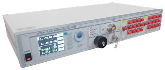
CM20 is SUNMA own research and development of high precision wide range of testing equipment. The main test is the light fraction of 1* 8,1 *16,1*24; 1*N shunt optical indicators include insertion loss, return loss. Return loss for lead and bare fiber testing, CM20 Cooperate with the computer progra
Ø built in 1310 and 1550 nm, 650 red breakpoint test.
Ø built-in high precision low power return loss test architecture, detection range up to 75 dB.
Ø IL test range 3dBm~-75dBm。
Ø Built-in optical power meter, synchronous wavelength switching.
Ø Small signal measuring input 1nw, inaccuracy is less than 0.1 dB。
Ø R232 serial port control, provide serial command, and can be automatically stored data
Ø Also showed insertion loss and return loss measurement results.
Electrical characteristics:
Ac power supply: 220VAC 50~60HZ @100mA Max.
Product operating temperature: 10℃~40℃
Product storage temperature: -5℃~60℃
 Safety tips:
Note: please use the 220v 3 phase power supply that is effectively connected to the ground. There is high voltage inside the instrument. For your safety, please do not disassemble the equipment.
l Please use the user manual for safe operating equipment.
l Before power, please check that the bottom line and the line of fire and the installation of the zero line is correct.
l High light power will burn out photosensitive detection, in order to make the detection of surface can work normally, please make sure the input light should not be more than 10 mw.
Test system includes 1 device:
2
l Mainly responsible for test the insertion loss and return loss, light switch to light switch output respectively to 1 * N divider test divider insertion loss and return loss.
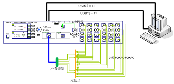
l Connect 1310/1550 return loss of output of PLC tester to 24 on the input end of the light switch. By controlling the switch of optical switch, the insertion loss and return loss values of all the heads of the shunt are tested respectively.
.1 divider PLC tester tests is need through the configuration bus bar length, the length of the bus and the overall length of fiber length on the default bus is 7 meters.
.2 The PLC tester is connected to the jumper FC/ APC-FC /APC at the input end of the optical switch with a length of 1 meter
.3 The fiber length inside the optical switch is 2 meters
.4 FC/APC-FC/APC Single line length of 1 m
.5 FC/APC-FC/UPC test lead 3 meters
.6 The total bus length is set at 7 meters
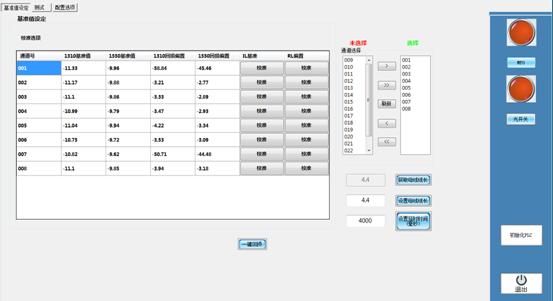
图3
l Not choice and choice:The number of channels not selected is 24, and the number of channels selected can be changed according to customer requirements.
l ![]() :Single channel selection
:Single channel selection ![]() :Select all channels
:Select all channels ![]() :Click refresh to select the number of channels that have been determined
:Click refresh to select the number of channels that have been determined
l ![]() :Number of unselected single channels
:Number of unselected single channels ![]() Cancel all channels
Cancel all channels

 Online Message
 Skype
Skype

