
Basics of Fiber Optic Polishing
Optical fiber is a good vehicle for high-speed data transmission as long as optical transmission is efficient. Fiber connector assemblies
play a key role in fiber optic communications. The translates need to polish connector end faces to optimize performance, and the finish
of a connectors end face determines the quality of its light wave transmission. Fiber polishing is a common way of surface preparations
for almost all glass-based fibers with cladding diameters larger than 200 microns to ensure the proper optical propagation.
The science of polishing is crystallized in a well designed machine.A machine that uses a specific polishing motion and is tested for
conformance to the industry standards will produce quality polished connectors with high levels of consistency from batch to batch.
When you want to purchase a mechanical polishing machine,What question should be asked with the manufacturers? Click here for more
buying guideline
The current industry Backreflection standard is <-55dB. A high level of Backreflection will cause transmission problems for systems
that depend on the speed and clarity of a fiber system, since thedesired high data rates can encounter bit errors if the signal is
distorted. We knonw connectors are commonly referred to as PC, SPC, UPC and APC, which describe connector end-faces and also relate
to the Backreflection designation.
Details are shown in the follow table:
| PC (Physical Contact) | SPC (Super Physical Contact) | UPC (Ultra Physical Contact) | APC (Angled Physical Contact) |
| Backreflection Value = -35db | Backreflection Value = -45db | Backreflection Value = <-55db | The angle of choice is 8°. This angle deflects Backreflection to <-65db. |
Insertion loss is the amount of optical power lost at the interface of two connectors. Poor insertionloss readings are generally a result
of fiber misalignment, separation between connections (also referred to as ‘air-gap’) and/or the quality of the finish on the end of
the connector.The currently stated standard for insertion loss is <0.5db, but the commonly expected level, has become <0.3db.
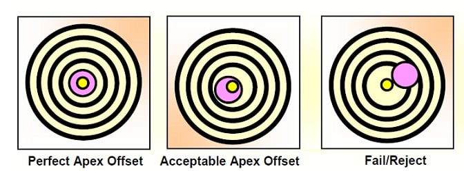
Apex defines the highest point on the spherical surface at the end-face of the connector. Apex offset is the measured distance between
the center of the fiber and the actual high point of a polished connector.An excessive apex offset contributes to high Insertion Loss
and high Backreflection readings. Follow figure shows the levels of the apex offset:
 Interference Fringes |
 Apex |
 Fiber |
 Center of fiber |
Radius of curvature is the measurement of a connectors end-face spherical condition.A proper radius,combined with an acceptable fiber
undercut, will optimize fiber-to-connector compression.The industry specification for radius of curvature is 10-25mm. This range allows f
or maximum connector performance.
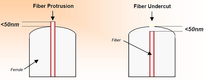
The undercut measures how far the fiber is recessed inside a connector ferrule, but it also may be possible for a fiber to protrude
above the ferrule. Both conditions directly result from the polishing process and can be measured with an interferometer. Excessive
Fiber Undercut is usually specified as more than 50nm. Fiber Undercut is a condition that affects both Backreflection and Insertion Loss.
When connectors are mated, the ferrule material surrounding the fiber compresses, which optimally allows fibers with an acceptable
undercut/protrusion to make contact. Fibers that do not make intimate contact have an air-gap. An air-gap will produce unacceptable
Backreflection & Insertion Loss measurements. Fiber undercut and protrusion:
Polishing Tips and Process Considerations
Polishing Films - Films are the most significant factor in your polishing operations. Quality and gradations vary from supplier to
supplier. When a polishing technique is developed the film type, make and particle size must be chosen carefully. Excessively
aggressive films can destroy a 125μm fiber, and the spherical radius can be disrupted beyond repair. Also,of critical importance
to real cost, is the initial cost of the polishing film as it relates to the cycle life that the films provide--this can vary
significantly from various manufacturers. Clean each piece of polishing film before and after each use. Cleanliness will increase
the film life and decrease the cost per connector.
Epoxy - different types of epoxies can be removed more easily with specific grades ofsilicon carbide polishing films. The films to
use on this step depend on the epoxy type and the size of the epoxy bead mounted on the connector end-face. Different epoxies have
varying levels of hardness--some are tacky, and some are firm--Hard epoxies are removed easily with coarser particle sized films
(20 um, 30 um, etc.), while softer epoxies are better suited to smaller particle sized films, i.e. 9 um, 5 um, etc. The epoxy bead
that remains on the connector before polishing should be minimized(the size of a pinhead). This will extend the life of
all the polishing films. Also, try differentgradations of silicon carbide until you find the epoxy removal film that works best for
yourneeds.
Cleanliness - A contamination free environment is essential when an optimum connector polish is desired. Deionized/Filtered Water,
Isopropyl Alcohol, Lint Free Tissues, Lint Free Swabs,Canned Airare are needed to minimize contamination. Check the reference
cable end-face periodically for end-face defects. Connecting and de-connecting will result in debris build-up over a period of time.
Clean the end-face with alcohol using a lint free tissue. Also, at some point in time the reference will need to be repolished.
After repeated re-polishing the reference cable will need to be replaced.
Lubrication - deionized water, filtered water and suspensions, when used correctly can result in enhanced connector performance.
The best solutions have very small particle sizes 20-60nm, at least half the size of the final polishing film, and can decrease
Return Loss by as much as 5dB. Dilute the filtered/deionized water may improve your performance.
Polishing Machine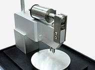 Have the capability to perform all types of polishing |
Fiber Curing Oven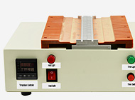 Heating for almost all kind of fiber optic connectors |
Central Pressure Polishing Jig For LC, SC, ST, FC,etc UPC/APC Connector |

 Online Message
 Skype
Skype

