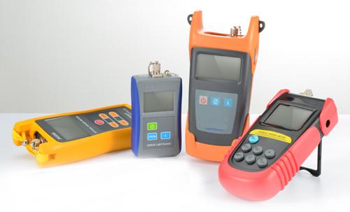
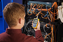
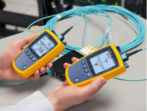
In fiber optic network, whether installing new cable, or troubleshooting existing cable, cable testing always plays an important role in the process. Optical power meter which is widely used for power measurement and loss testing is well known to us. Today, we are going to talk about this familiar and essential fiber optic tester - optical power meter,

As its name suggests, optical power meter is a meter which is used for testing optical power. So, what is optical power? And how to measure power by using optical power meter?
In simple terms, optical power is the brightness or “intensity” of light. In optical networking, optical power is measured in “dBm” which refers to a decibel relative to 1 milliwatt (mW) of power. Thus a source with a power level of 0 dBm has a power of 1 mW. Likewise, 3 dBm is 2 mW and -3 dBm is 0.5 mW, etc. And one more thing should be known is that 0 mW is negative infinity dBm.

Measuring power at the transmitter or receiver requires only an optical power meter, an adapter for the fiber optic connector on the cables used, and the ability to turn on the network electronics.
The optical power meter must be set to the proper range (usually dBm, but sometimes mW) and the proper wavelength when measuring power. When all are ready, attach the optical power meter to the cable at the receiver to measure receiver power, or to a short test cable that is attached to the system source to measure transmitter power. Mark the value, and compare it to the specified power for the system and make sure it is in the acceptable range for the system.
In addition to measuring optical power, optical power meter can be used to test optical lost by using together with light source. What is optical loss and how does the optical power meter achieve loss testing?
When light travels through fiber, some energy is lost, e.g., absorbed by the glass particles and converted to heat; or scattered by microscopic imperfections in the fiber. We call this loss of intensity “attenuation”. Attenuation is measured in dB loss per length of cable. dB is a ratio of two powers. Even the best connectors and splices aren’t perfect. Thus, every time we connect two fibers together, we get loss. We called this loss as insertion loss which is the attenuation caused by the insertion of the device such as a splice or connection point to a cable. Actual loss depends on your fiber connector and mating conditions. Additionally, insertion loss is also used to describe loss from Mux since it is the “penalty you pay just for inserting the fiber”.

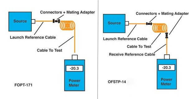
Loss of a cable is the difference between the power coupled into the cable at the transmitter end and what comes out at the receiver end. But Loss testing requires not only optical power meter, but also a light source. In general, multimode fiber is tested at 850 nm and optionally at 1300 nm with LED sources. Single-mode fiber is tested at 1310 nm and optionally at 1550 nm with laser sources. The measured loss is compared to the loss budget, namely estimated loss calculated for the link. In addition, in order to measure loss, it is necessary to create reproducible test conditions for testing fibers and connectors that simulate actual operating conditions. This simulation is created by choosing an appropriate source and mating a launch reference cable with a calibrated launch power that becomes the “0 dB” loss reference to the source.
There are two methods used to measure loss which are called “single-ended loss” and “double-ended loss”. Single-ended loss works by using only the launch cable while the double-ended loss works using a received cable attached to the meter also. The method “signle-ended loss” is described in FOTP-171. By using this method, you can test the loss of the connector mated to the launch cable and the loss of any fiber, splices or other connectors in the cable you are testing. Thus, it is the best possible method of testing patchcords, since it tests each connector individually. The method “double-ended loss” is specified in OFSTP-14. In this way, you can measure loss of two connectors and the loss of all the cable or cables, including connectors and splices in between. The following picture shows these two methods to us. From left to right: Single-ended loss testing (Patch Cord), Double-ended loss testing (installed cable plants).

As described above, optical power meter is very useful and necessary for fiber optic testing such as optical power measurement and loss testing. Thus, to select a suitable optical power meter is very important. According to the user’s specific application, several points should be considered when choosing an optical power meter:
In addition to optical power meter and light source, other tools such as launch cable, mating adapters, visual fault locator or fiber tracer, cleaning and inspection kits as well as other testers are also required for fiber optic testing. SunmaFiber offers a comprehensive solution of fiber optic testers and tools which help you achieve a reliable and valuable fiber optic system. Contact us via sales@SunmaFiber.com for more information.
Tags: loss testing, optical power meter, power measurement