
When light leaves the end of an optical fiber, it immediately begins to diverge. This is not a problem when the fiber is connected directly to another fiber component, but many optical systems require the signal to travel through free space before reaching a lens, detector, modulator, filter or second fiber.
A fiber optic collimator converts this diverging fiber output into a low-divergence free-space beam. It can also operate in reverse, focusing an incoming free-space beam into an optical fiber.
Fiber collimators are widely used in:
Selecting the correct collimator requires more than matching the connector. Wavelength, fiber type, mode-field diameter, focal length, beam diameter, divergence, polarization performance and return loss all affect system performance.
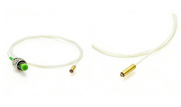
A fiber optic collimator is an optical assembly that provides an interface between guided light inside a fiber and a free-space optical beam.
In the fiber-to-free-space direction, it:
In the reverse direction, it:
Two matched collimators can therefore create a free-space section between two optical fibers. This allows filters, isolators, beam splitters, modulators and other free-space components to be inserted into an otherwise fiber-based system. Alignment is critical because lateral, angular and axial errors are often major contributors to coupling loss.
No optical beam is perfectly parallel.
A fiber collimator produces a beam with a small but finite divergence angle. Diffraction prevents a finite-diameter beam from remaining perfectly constant over an unlimited distance.
For a single-mode fiber whose output can be approximated as a Gaussian beam, the full divergence angle after collimation is approximately related to:
A longer focal length generally produces:
A shorter focal length generally produces:
Thorlabs uses the ratio of mode-field diameter to focal length to estimate full-angle divergence for single-mode fiber. The same approximation is less accurate for multimode fiber because multimode output usually does not have a simple Gaussian intensity profile.
In a simplified fixed-focus design, the fiber end is positioned near the focal plane of the lens.
Light from the fiber expands before entering the lens. The lens changes the wavefront curvature so that the output beam has low divergence.
The reverse process occurs when coupling free-space light into a fiber. The lens must create a focal spot that matches the fiber’s guided mode as closely as possible.
For efficient coupling into a single-mode fiber, the focused field must match the fiber mode in:
Mode-field diameter is generally more useful than physical core diameter when calculating coupling conditions for a single-mode fiber. Newport notes that efficient single-mode coupling requires matching the incident field distribution to the fiber mode rather than simply focusing light somewhere inside the core.
For a Gaussian single-mode beam, the approximate 1/e² collimated beam diameter can be expressed as:
Beam diameter ≈ 4λf ÷ (π × MFD)
where:
This relationship shows why a single collimator does not produce the same beam diameter at every wavelength or with every fiber.
The formulas are useful for initial selection, but actual results can differ because of:
Thorlabs uses wavelength, focal length and mode-field diameter to estimate both output beam diameter and divergence for its single-mode collimators.
A collimator and a focuser use similar optical elements but are configured for different output conditions.
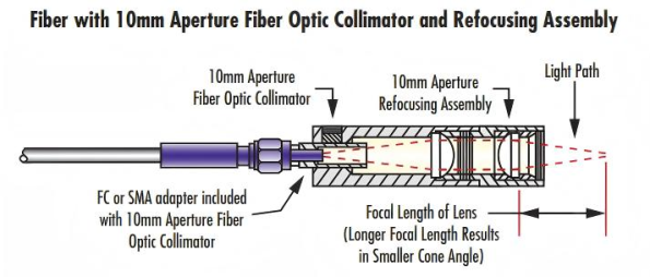
A fiber collimator is adjusted to produce a low-divergence beam that maintains an approximately constant diameter over a useful propagation distance.
Typical uses include:
A fiber focuser is configured to produce a small optical spot at a finite working distance.
Typical uses include:
OZ Optics distinguishes collimators and focusers by whether the assembly is intended to create a desired free-space beam diameter or a focused spot size. Both may be used in source-to-fiber and fiber-to-detector coupling systems.
Fiber collimators can be classified by optical design, fiber type, package style and adjustment mechanism.
A GRIN lens uses a radial refractive-index gradient rather than only curved surfaces to control the optical beam.
GRIN collimators are typically:
They are widely used in compact optical components and matched collimator pairs.
GRIN assemblies are commonly factory aligned for a particular wavelength. Thorlabs offers GRIN fiber collimators for applications such as fiber-to-fiber free-space coupling, laser-diode coupling and detector illumination.
An aspheric lens has a non-spherical surface designed to reduce spherical aberration.
A single aspheric element can provide good beam quality while maintaining a compact package. This makes it a common choice for single-mode fiber collimation and laser-diode coupling.
Fixed aspheric collimators are often factory aligned for a specific wavelength. Although they may transmit other wavelengths within the coating range, minimum divergence is normally achieved near the design wavelength.
Achromatic collimators use two or more lens elements to reduce wavelength-dependent focal shift.
They are useful for:
Compared with a simple aspheric lens, an achromatic design can maintain more consistent collimation across a wider spectral range.
The trade-offs may include:
Broadband AR coatings are normally applied to reduce surface-reflection losses.
Reflective collimators commonly use an off-axis parabolic mirror instead of a refractive lens.
Because reflection does not depend on glass dispersion in the same way as refraction, the mirror’s focal length remains substantially constant over a broad wavelength range.
Reflective collimators are particularly useful for:
Thorlabs’ reflective collimators use off-axis parabolic mirrors and are specifically positioned as broadband alternatives to refractive collimators.
A C-lens is a compact cylindrical lens commonly used in miniature telecom optical assemblies.
It may be selected for:
C-lens collimators can provide small beam diameters and low-back-reflection designs in compact housings. Commercial examples are available with single-mode or PM fiber, APC termination and beam diameters specified at the 1/e² intensity level.
A single-mode collimator is designed around the mode-field diameter of a specific fiber at a defined wavelength.
It generally produces:
The fiber part number matters because two single-mode fibers can have different mode-field diameters at the same wavelength.
A multimode collimator must accommodate a larger core and a distribution of guided modes.
Its output may have:
Single-mode Gaussian formulas should not be used uncritically for multimode collimator selection.
A PM fiber collimator is designed to preserve the launched polarization state when light is correctly aligned to one of the fiber’s principal axes.
Important PM specifications may include:
The connector key is commonly aligned to a specified PM axis, but the convention must be confirmed before ordering.
Commercial PM collimator examples demonstrate why universal specifications should be avoided. Depending on design, products may specify extinction ratios above 20 dB and return-loss values around 55–60 dB, but these are product-specific rather than mandatory values for all PM collimators.
Dual-fiber assemblies position two fibers within one ferrule or V-groove structure.
They may be used in:
For PM dual-fiber assemblies, both fiber positions and polarization axes must be controlled. The slow axes may be aligned parallel or perpendicular depending on the application.
A fixed collimator is factory aligned and contains no user-adjustable focusing mechanism.
Factory-aligned collimation packages are commonly optimized to provide minimum divergence at a specified design wavelength.
An adjustable collimator allows the axial distance between the fiber tip and lens to be changed.
This correction is important:
The adjustment generally changes the fiber-to-lens spacing; it does not change the inherent focal length of the lens.
Rotating or translating the adjustment barrel moves the lens relative to the fiber tip, allowing the user to optimize beam collimation or produce a slightly converging or diverging output.
The fiber is permanently attached and aligned to the lens assembly.
Advantages include:
Possible terminations include:
A connectorized patch cable is inserted into a receptacle, commonly FC/PC, FC/APC or SMA.
Advantages include:
Receptacle collimators must account for connector tolerances and the beam deviation associated with angled physical-contact interfaces.
The operating wavelength must match:
A refractive collimator may operate away from its design wavelength, but beam divergence and focal position can change because of chromatic aberration.
Beam diameter should always include its measurement definition.
The most common definition for a Gaussian beam is:
1/e² intensity diameter
Other definitions, including FWHM, produce different numerical values.
A specification stating only “1 mm beam” is incomplete unless the measurement convention is defined.
Confirm whether divergence is specified as:
Confusing full-angle and half-angle values produces a two-to-one error.
The measurement distance and beam-diameter definition should also be documented.
Longer focal length generally produces a larger beam with lower divergence for a given wavelength and single-mode fiber.
However, the lens diameter must be large enough to avoid clipping the beam.
NA may refer to:
These are not automatically the same value.
A lens must have sufficient NA to collect the diverging fiber output, but specifying a very high lens NA does not by itself guarantee high coupling efficiency or low wavefront error.
For a fiber-to-free-space collimator, insertion loss must be defined by a specific measurement configuration.
It may include:
A claim such as “insertion loss below 0.5 dB” is meaningful only when the test setup, wavelength, fiber and alignment method are stated.
Tests with two matched collimators show that alignment strongly influences fiber-to-fiber coupling efficiency, particularly for single-mode fiber.
Back-reflected light can destabilize lasers, increase noise and interfere with coherent or interferometric measurements.
Back reflection may be reduced through:
UPC and APC interfaces must not be directly mated.
Wavefront error indicates how much the output wavefront deviates from the intended shape.
It may be important in:
Values such as λ/10 apply only under specified wavelength, aperture and measurement conditions and should not be presented as a universal collimator requirement.
Extinction ratio is important for PM collimators.
It depends on:
The collimator cannot restore a polarization state that was incorrectly launched into the PM fiber.
High-power applications require evaluation of:
Contamination at the fiber or lens surface can absorb light and produce localized heating.
A device advertised as “high power” should include a tested power level, wavelength, beam condition and damage criterion.
Temperature changes can alter:
For demanding systems, review:
| Selection Factor | Questions to Confirm |
|---|---|
| Operating wavelength | What is the nominal wavelength and required spectral range? |
| Fiber type | Single-mode, multimode or polarization-maintaining? |
| Fiber specification | What are the exact fiber type, MFD and NA? |
| Optical direction | Fiber-to-free-space, free-space-to-fiber or bidirectional? |
| Beam diameter | What 1/e² output diameter is required? |
| Divergence | What full-angle or half-angle limit is acceptable? |
| Lens design | GRIN, aspheric, achromatic, C-lens or reflective? |
| Bandwidth | Monochromatic, tunable or broadband source? |
| Package | Pigtailed, receptacle, fixed or adjustable? |
| Polarization | Is PM fiber required, and which axis should align with the key? |
| Reflection | What return loss or back-reflection limit is required? |
| Optical power | Continuous-wave or pulsed, and at what peak power? |
| Environment | What temperature, vibration and stability requirements apply? |
| Mounting | Is tip, tilt, XYZ or six-axis adjustment required? |
| Testing | Are beam diameter, divergence, IL, RL or ER reports required? |
Matched collimators create a free-space beam inside devices such as:
OZ Optics lists WDM packaging, integrated optics, source-to-fiber coupling and detector coupling among common collimator applications.
PM and high-power collimators may be used to direct fiber-laser output into:
Power handling and back reflection require particular attention.
Broadband and achromatic collimators are useful where several wavelengths must share the same optical path.
Relevant parameters include:
Fiber collimators are used in:
Environmental stability may be more important than minimum laboratory insertion loss.
Two collimators can bridge a short free-space gap between fibers.
Possible applications include:
Misalignment is frequently a dominant source of loss in a matched collimator system, so mechanical stability is as important as lens quality.
Two FC/APC collimators may have different fibers, focal lengths, wavelengths and beam diameters.
A lens may transmit the signal but still produce excessive divergence away from its alignment wavelength.
Single-mode beam calculations should normally use MFD rather than nominal core diameter.
Multimode output depends on its mode distribution and launch condition.
The NA printed for the internal lens is not necessarily the effective NA of the complete assembly.
Most adjustable collimators translate the lens relative to the fiber; they do not change the lens’s optical focal length.
An angled fiber end can produce an output beam that is not exactly parallel to the mechanical housing axis. The mount must allow for this geometry.
Insertion loss, return loss, divergence and extinction ratio must be evaluated for the exact wavelength, fiber and package.
It converts divergent light from an optical fiber into a low-divergence free-space beam or couples an aligned free-space beam into a fiber.
No. The beam always has finite divergence because of diffraction and optical imperfections.
The primary factors are wavelength, fiber mode-field diameter, lens focal length and fiber-to-lens spacing.
No.
A longer focal length can reduce divergence and increase beam diameter, but it also increases package size and may require a larger clear aperture.
Possibly, but performance depends on lens design and coating.
Achromatic or reflective collimators are generally more suitable for broadband operation than simple fixed aspheric designs.
Mechanical compatibility does not guarantee suitable optical performance. The lens and alignment must match the fiber mode and required beam characteristics.
Focal length is an optical property of the lens.
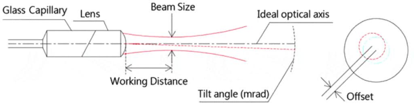
Working distance normally refers to a practical distance between the optical assembly and a target, focus or mating component. For a collimator, the fiber tip is positioned near the lens focal plane, but this internal spacing is not the same as an external working distance.
For a Gaussian beam, the Rayleigh range describes the distance around the beam waist over which the beam area remains within a defined factor of its minimum value.
It is a beam-propagation parameter, not simply the focal length or mechanical working distance.
APC generally provides lower back reflection, but it also produces an angled beam geometry and must match the rest of the optical interface.
The correct choice depends on return-loss requirements, packaging and alignment.
Confirm the PM fiber type, operating wavelength, extinction ratio, axis orientation, connector-key alignment, beam diameter and return-loss requirement.
Fiber optic collimators provide a controlled interface between guided fiber modes and free-space optical beams.
Their performance depends on the complete optical system rather than on one specification alone. Wavelength, fiber MFD or NA, focal length, lens design, beam diameter, divergence, return loss, polarization and mechanical stability must all be considered.
GRIN and C-lens collimators provide compact solutions for miniature optical packages. Aspheric lenses offer strong monochromatic performance, while achromatic and reflective designs are more suitable for broadband systems. PM collimators add polarization-axis and extinction-ratio requirements, and adjustable designs allow the fiber-to-lens spacing to be optimized during setup.
Sunma supplies customizable fiber optic collimators for single-mode, multimode and polarization-maintaining applications. Available configurations may include GRIN, C-lens and aspheric designs, fixed or adjustable structures, different beam diameters, operating wavelengths, fiber lengths and connector options. Final specifications should be defined according to the exact optical source, fiber, beam requirement and operating environment.

 English Home
 简体中文
简体中文 Online Message
 Skype
Skype
 QQ:20181072

