
Modern data centers need to connect high-density optical ports to large numbers of conventional LC interfaces without creating unmanageable bundles of individual patch cords.
An MPO-to-LC breakout cable provides this transition by combining several fibers at the MPO end and separating them into individual LC connectors or duplex LC channels at the opposite end.
These assemblies are widely used for:
However, an MPO-to-LC cable is not universally compatible with every MPO port. Fiber count, active lane assignment, connector gender, polarity, key orientation and polish type must match the optical transceiver and network architecture.
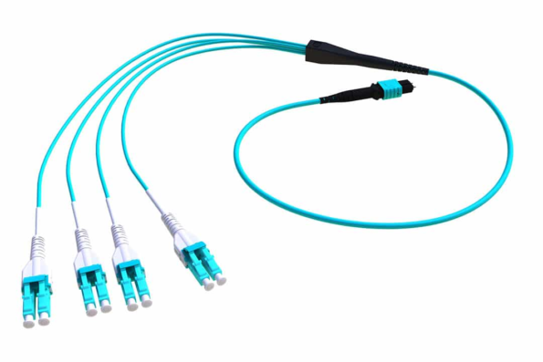
An MPO-to-LC cable is a pre-terminated multi-fiber assembly with:
The MPO end consolidates multiple fibers into a compact interface. The LC ends separate those fibers into channels that can connect to conventional LC transceivers, adapters or patch-panel ports.
A typical assembly may be described as:
These configurations are not interchangeable. The correct design depends on the number of active fibers and the lane mapping required by the connected equipment.
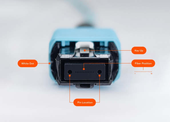
MPO stands for Multifiber Push-On.
An MPO connector aligns several optical fibers inside a rectangular MT ferrule. Common interfaces include MPO-8, MPO-12, MPO-16 and MPO-24 configurations.
A high-fiber-count cable such as a 48-, 72- or 144-fiber trunk normally uses several MPO connectors or subunits. It does not place every fiber inside one ferrule.
For example, a commercial 144-fiber MPO trunk may contain twelve 12-fiber subunits with twelve MPO-12 connectors at each end.
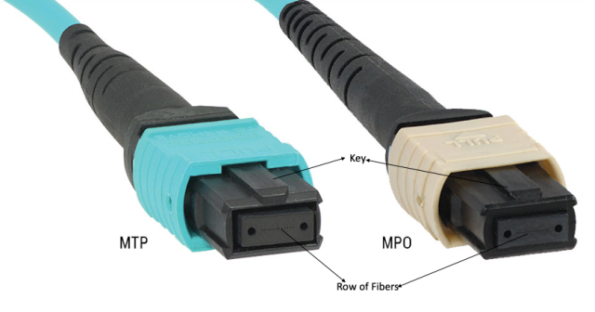
MPO is the generic multi-fiber connector interface.
MTP is a registered connector brand developed by US Conec. It is designed as a higher-performance MPO connector and complies with relevant MPO interface standards.
A standards-compliant MTP connector can mate with a compatible generic MPO connector, provided that the following parameters match:
MTP should therefore be described as a type of MPO connector rather than as a completely separate interface.
These two products serve different purposes.
| Feature | MPO-to-LC Breakout Cable | MPO Trunk Cable |
|---|---|---|
| End A | MPO | MPO |
| End B | Multiple LC connectors | MPO |
| Primary function | Separate MPO fibers into LC channels | Connect two high-density MPO points |
| Common installation | Equipment breakout and patching | Backbone and panel-to-panel connection |
| Typical fiber counts | 8, 12, 16 or 24 per breakout group | 12 to several hundred total fibers |
| Equipment connection | Can connect directly to LC ports | Usually connects panels, cassettes or MPO transceivers |
A trunk carries multiple fibers between two distribution locations. A breakout cable converts those fibers into individual equipment-facing connections.
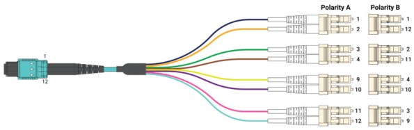
This configuration uses:
The four center positions of the MPO-12 ferrule are normally unused in an SR4 application.
Typical uses include:
Cisco documents 40GBASE-SR4 breakout through an external MPO parallel-to-duplex cable connecting one 40G port to four 10G optical interfaces. Compatible 100G SR4 platforms can similarly use an MPO-12-to-4×LC assembly for 4×25G breakout.
The switch, optical module and operating software must all support breakout mode. A passive cable cannot independently convert one Ethernet rate into another.
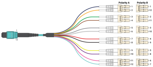
This assembly uses all twelve fibers as six duplex LC channels.
It may be used for:
It should not be confused with an SR4 breakout cable, which normally uses only eight active fibers and four duplex LC channels.
This configuration separates every fiber into an individual simplex LC connector.
It can be useful for:
The labeling and mapping of every LC leg must be clearly documented.
An MPO-16 assembly contains sixteen active fiber positions and can be divided into eight duplex LC channels.
This format may be associated with eight-lane parallel-optics applications. For example, some 400GBASE-SR8 modules use an MPO-16 interface and can support specific breakout configurations.
MPO-16 has a different key position and ferrule layout from conventional MPO-12 and MPO-24 connectors. It should not be treated as mechanically interchangeable with them.
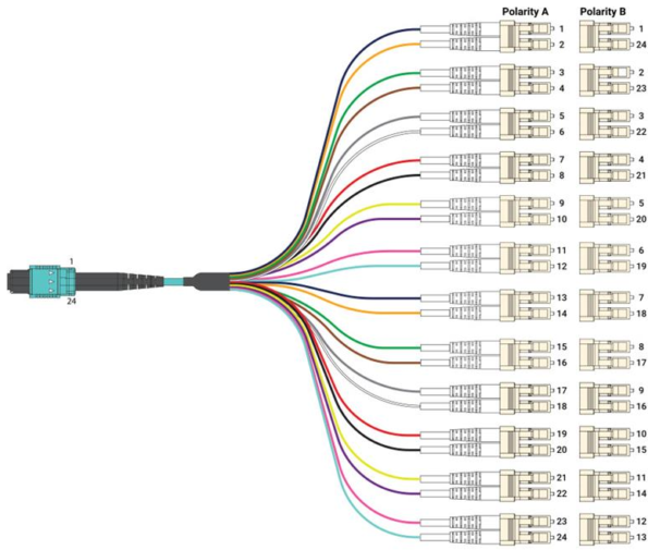
An MPO-24 assembly can be separated into twelve duplex LC channels.
It is used in:
The specific channel mapping must be confirmed because MPO-24 assemblies can be wired in different ways.
A conventional 40GBASE-SR4 interface contains:
Although the module uses an MPO-12 connector, only the outer eight fiber positions are used. The middle four positions remain unused.
An MPO-12-to-4×duplex-LC cable maps each transmit-and-receive pair to one 10G LC duplex channel.
The final architecture is:
One 40G QSFP+ port → Four 10G SFP+ ports
Cisco notes that only specific 40G modules support 4×10G breakout. Some SR4 variants support native 40G operation but do not support breakout, so the transceiver datasheet must be checked before ordering the cable.
A conventional 100GBASE-SR4 interface uses:
An MPO-12-to-4×duplex-LC breakout cable can connect a compatible 100G QSFP28 port to four 25G SFP28 ports.
The final architecture is:
One 100G QSFP28 port → Four 25G SFP28 ports
The host platform must support 4×25G port breakout, and the optical modules at both ends must be interoperable. Cisco lists MPO-12-to-4×LC external MMF and SMF breakout configurations for supported 100G SR4 and PSM4 optics.
It depends on the optical interface.
“400G” alone does not determine the connector or cable type. Current 400G modules may use:
| Optical Interface | Typical Fiber Interface |
|---|---|
| 400GBASE-SR8 | MPO-16 multimode |
| 400GBASE-DR4 | MPO-12 single-mode |
| 400GBASE-SR4.2 | MPO-12 multimode |
| 400GBASE-FR4 | Duplex LC single-mode |
| 400G BiDi | Duplex LC multimode |
| 4×100G breakout optics | MPO-12 with four duplex branches |
Cisco’s current 400G portfolio includes MPO-16, MPO-12 and duplex-LC products, demonstrating that there is no universal “400G MPO-to-LC cable.”
Always select the cable from the exact optical module part number and breakout matrix.
MPO-to-LC cables allow one high-density MPO interface to serve several LC-based ports.
This is useful in:
A properly designed breakout reduces the number of full-length individual LC patch cords that must be routed through the cable pathway.
An MPO trunk may run between two racks or distribution areas. At the equipment end, an MPO-to-LC harness or cassette converts the trunk into individual LC ports.
Two common approaches are:
The MPO trunk connects directly to an MPO-to-LC breakout assembly.
Advantages:
The MPO trunk connects to a cassette containing internal MPO-to-LC fan-out.
Advantages:
The preferred approach depends on accessibility, density, loss budget and maintenance procedures.
A breakout cable may connect one high-speed switch port to several lower-speed server or network-adapter ports.
For example:
Support must be confirmed in the switch configuration and transceiver interoperability documentation.
MPO-to-LC fan-out cables are also used to access individual fibers for:
Clearly numbered LC legs are particularly important in these applications.
Several fiber channels are consolidated into one MPO connector, reducing the number of connectors required on the high-density side.
The assembly is terminated, polished and tested at the factory. Installation normally involves routing, mating and verifying the cable rather than performing field termination.
The actual labor saving depends on the network design and should not be expressed as a universal percentage.
A single grouped assembly can be easier to route than multiple unrelated patch cords.
Benefits may include:
A correctly designed trunk-and-breakout system can support changes between native parallel connections and lower-rate LC connections.
This provides migration flexibility, but it does not guarantee compatibility with every future optical standard.
Professional assemblies can be supplied with:
Performance must be evaluated using the stated test method and exact connector configuration.
An MPO connector only defines the physical interface. The transceiver and switch must support the desired lane separation.
A cable with the correct connector types can still fail if its transmit and receive lanes are mapped incorrectly.
One contaminated MPO ferrule can affect several fibers simultaneously.
Individual LC legs are smaller and more vulnerable than the main cable body. Poor routing can place excessive tension on the fan-out point.
Changing from MPO-12 to MPO-16, changing fiber mode or adopting a different channel mapping may require a new cable assembly.
Do not order from the Ethernet speed alone.
Record:
A 100G SR4 module and a 100G LR4 module both carry 100G, but the former may use MPO while the latter commonly uses duplex LC.
Common categories include:
For standard Cisco SR4 examples:
Actual reach must be taken from the exact transceiver datasheet.
OS2 assemblies are used with compatible parallel single-mode interfaces such as:
Single-mode MPO connectors may require an angled end face, depending on the transceiver specification. Cisco’s breakout guidance identifies angled MPO end faces for several single-mode parallel-optics applications.
Do not assume that an MPO-12 port uses all twelve positions.
Examples:
The cable must match the active-lane arrangement rather than only the connector name.
MPO connectors are available as:
A mated pair normally requires one male and one female connector.
Many pluggable optical modules have pinned MPO interfaces and therefore require a female cable connector, but the equipment specification must always be checked.
Two male connectors should not be mated because their guide pins interfere. Two female connectors lack the pins required for controlled ferrule alignment.
The cable must connect transmitter lanes at one end to receiver lanes at the other.
Relevant details may include:
For a direct MPO-to-MPO SR4 link, Method B is commonly used. An MPO-to-LC harness uses an application-specific fan-out map and should be ordered according to the transceiver pinout rather than by polarity terminology alone.
Common possibilities include:
UPC and APC end faces must not be directly mated.
Parallel single-mode optics frequently use angled MPO interfaces, while multimode SR applications generally use UPC MPO interfaces. The exact module datasheet remains the controlling requirement.
Confirm:
Staggered breakout lengths may improve routing when LC ports are arranged in different positions across a switch or patch panel.
The complete link may include:
Each connection adds loss.
Do not rely on universal values such as “0.3 dB for LC and 0.5 dB for MPO.” Standard-loss and low-loss products have different limits, and actual results depend on the fiber mode, polish and test method.
Request measured insertion-loss results for every channel when the loss budget is tight.
LSZH, Riser and Plenum should be specified separately.
Low Smoke Zero Halogen describes a jacket designed to limit smoke and halogen emissions under specified fire tests.
Riser-rated cable is intended for vertical building pathways under the applicable regional code.
Plenum-rated cable is designed for environmental air-handling spaces and is held to stricter flame- and smoke-performance requirements in markets where that classification applies.
Fire requirements vary by country and region. A generic LSZH jacket is not automatically approved for a North American plenum space.
For critical data center installations, request:
SR4 applications normally use eight active positions.
A 40G SR4 breakout normally requires four duplex LC connectors, not twelve simplex connectors.
The cable cannot make an unsupported switch port operate as four independent ports.
A 144-fiber trunk normally contains multiple MPO connectors or subunits.
Guide-pin configuration must match the module, adapter or mating cable.
The different end-face geometries can cause high loss, reflection and connector damage.
Incorrect lane mapping may produce no link even when every connector fits physically.
Fire and smoke requirements depend on the exact standard and installation region.
Future optics may use MPO-12, MPO-16, MPO-24, duplex LC, CS, SN or other interfaces.
No.
An MPO-to-LC cable breaks a multi-fiber MPO interface into LC channels. An MPO trunk has MPO connectors at both ends.
It depends on the application.
Possible configurations include:
SR4 requires four transmit lanes and four receive lanes. The four central MPO-12 positions are unused.
Yes, when the switch and 40G optical module support 4×10G breakout and the correct MPO-to-4×LC cable is used.
Yes, when the host platform and optics support 4×25G breakout.
Certain 400G breakout applications can use MPO-to-LC cables, but other 400G modules require MPO-16, native MPO-12 or duplex LC connections. Check the exact transceiver.
MTP is a high-performance branded MPO connector. Compatibility and performance still depend on the complete assembly and specification.
Choose the fiber specified by the optical transceiver.
OM4 is widely used for short-reach multimode SR links. OS2 is used for parallel single-mode and longer-reach applications.
Yes, provided that the switch port, server adapter, optical modules, fiber type and breakout mapping are compatible.
No.
High-fiber-count trunks typically use several MPO connectors or subunits. A 144-fiber assembly may use twelve MPO-12 connectors at each end.
MPO-to-LC breakout cables provide an efficient transition between high-density parallel-fiber interfaces and conventional LC equipment ports.
Their primary value lies in:
However, the connector shape alone does not determine compatibility. Before ordering, confirm:
Sunma supplies customizable MPO-to-LC breakout cables with OS2, OM3, OM4 and OM5 fiber options. Available configurations can include MPO-8, MPO-12, MPO-16 and MPO-24 interfaces, simplex or duplex LC fan-outs, custom leg lengths, polarity mapping, low-loss connectors and application-specific jacket materials. Final cable construction should always be based on the exact transceiver interface and network topology.

 English Home
 简体中文
简体中文 Online Message
 Skype
Skype
 QQ:20181072

