
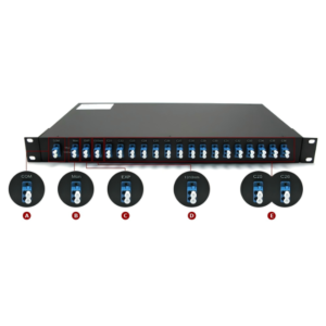
You are staring at two quotes on your screen. Option A: a CWDM mux/demux pair with eight uncooled SFP+ transceivers, total system cost $2,400. Option B: a DWDM solution with the same channel count, cooled lasers, and an AAWG filter, total system cost $12,000. Both deliver 80 Gbps over a single fiber. Both are protocol-transparent. Both use standard single-mode fiber.
So why the 5× price gap? And more importantly—which one do you actually need?
The answer is not “DWDM is better.” The answer is: it depends on whether your network can tolerate a 6.3-nanometer wavelength drift.
This guide dismantles the marketing gloss and explains the physics, economics, and engineering trade-offs that separate these two WDM technologies. By the end, you will know exactly which technology pays for itself—and which one bleeds money on capabilities you will never use.
Wavelength Division Multiplexing (WDM) sends multiple optical signals through a single fiber by assigning each data stream a unique wavelength. The difference between DWDM and CWDM is not philosophical. It is mathematical.
| Parameter | CWDM (Coarse) | DWDM (Dense) |
|---|---|---|
| Channel spacing | 20 nm (~2,500 GHz at 1550 nm) | 0.8 nm (100 GHz) or 0.4 nm (50 GHz) |
| Wavelength grid | 1271–1611 nm (ITU-T G.694.2) | C-band (1530–1565 nm), L-band (1565–1625 nm) |
| Max channels | 18 (practically 8 on legacy fiber) | 40–96+ (up to 160 at 50 GHz) |
| Laser type | Uncooled DFB | Cooled DFB/EML with TEC |
| Amplification | Not possible (outside EDFA window) | EDFA-supported (C+L bands) |
| Max distance | ~80 km (passive) | 1,000+ km (with amplification) |
| Relative cost | ~30% of DWDM | Baseline |
That 20 nm vs. 0.8 nm spacing is not an arbitrary specification. It is the root cause of every downstream difference: cost, power consumption, thermal design, and scalability.
A Distributed Feedback (DFB) laser shifts its emission wavelength with temperature at a rate of approximately 0.08–0.10 nm per °C.
In an industrial temperature range of −40°C to +85°C (a 125°C swing), the total drift can reach 10 nm. Even over a narrower commercial range of 0°C to 70°C, the drift is ~6.3 nm.
DWDM channels are spaced 0.8 nm apart. A 6.3 nm drift means your laser will wander across eight neighboring channels. Without active stabilization, the system collapses into crosstalk chaos.
CWDM channels are spaced 20 nm apart. That same 6.3 nm drift stays comfortably within the channel’s ±6.5 nm tolerance window.
A Thermoelectric Cooler (TEC) is a solid-state heat pump that holds the laser chip at a precise setpoint (typically 25°C ±0.1°C) regardless of ambient conditions. It requires:
Removing the TEC is what makes CWDM transceivers 3 to 5 times cheaper and significantly lower in power.
But this freedom comes with a cost: CWDM lasers cannot be amplified by EDFAs (Erbium-Doped Fiber Amplifiers), which operate almost exclusively in the C-band (1530–1565 nm). Most CWDM channels sit outside this window. Without amplification, CWDM links are limited to the optical power budget of the transceivers themselves—typically 40–80 km depending on fiber quality and channel wavelength.
Engineering Insight: The 1391 nm water-peak region in legacy G.652 fiber introduces ~0.5 dB/km excess loss. CWDM channels near 1391 nm (the E-band) are effectively unusable on older fiber. Modern low-water-peak G.652.C/D fiber removes this restriction, but verify your fiber spec before planning an 18-channel CWDM deployment.
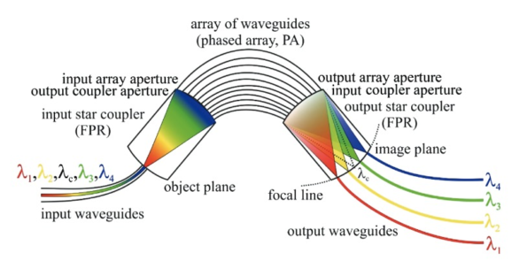
An Arrayed Waveguide Grating (AWG) is the engine of modern DWDM multiplexing. It is a planar lightwave circuit (PLC) fabricated on a silica substrate. Light enters a multimode interference region, splits into an array of waveguides with precisely incrementing path lengths, and recombines in a second coupler. The wavelength-dependent phase shift causes each channel to focus on a different output port.
The problem: silica’s refractive index changes with temperature (~1×10⁻⁵ /°C). A 40°C ambient swing shifts the central wavelength of each channel by ~0.12 nm—enough to misalign a 50 GHz-spaced DWDM grid.
| Feature | Thermal AWG (TAWG) | Athermal AWG (AAWG) |
|---|---|---|
| Temperature control | Active heater/TEC | Passive compensation |
| Power consumption | 3–5 W per device | 0 W |
| Temperature range | Controlled environment | −40°C to +85°C |
| Reliability | Active component = failure point | Fully passive |
| Cost | Lower upfront, higher OPEX | Higher upfront, zero OPEX |
AAWG achieves athermalization through two passive techniques:
The result is a device that holds its wavelength grid to within ±0.02 nm across the full industrial temperature range—with no power, no software, and no maintenance.
Specification Benchmark: A typical 48-channel AAWG module delivers insertion loss ≤5.5 dB, adjacent channel isolation ≥25 dB, non-adjacent isolation ≥30 dB, and PDL <0.5 dB. These figures meet the requirements of 100G/400G coherent DWDM systems.
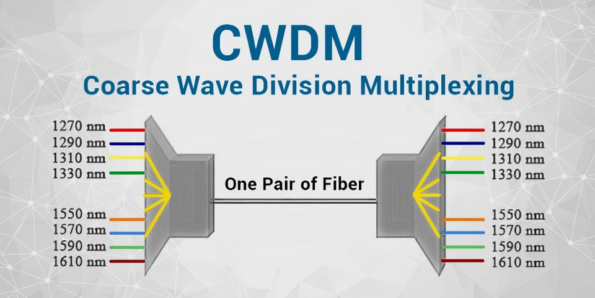
While DWDM relies on AWG interference, CWDM typically uses Thin-Film Filter (TFF) technology. TFFs are cascaded dielectric interference filters, each reflecting all wavelengths except one narrow passband. They are simpler to manufacture, offer extremely high isolation (>45 dB non-adjacent), and are inherently athermal because the filter’s center wavelength is determined by physical layer thickness, not waveguide path length.
| Package | Form Factor | Best For | Typical IL |
|---|---|---|---|
| ABS Box | 100×80×10 mm | Field splices, outdoor closures | ≤2.6 dB (8-ch) |
| FMU Plug-in | 1/4 rack unit | High-density patching | ≤2.6 dB (8-ch) |
| 1U Rackmount | 19″ rack, 44 mm height | Centralized management | ≤4.5 dB (16-ch) |
| LGX Module | 130×30×130 mm | Telecom ODF integration | ≤2.6 dB (8-ch) |
CWDM modules also offer practical features absent from basic DWDM muxes:
Both technologies are protocol-transparent. A WDM mux does not care if the payload is 1G Ethernet, 16G Fibre Channel, or 100G coherent. The transceiver determines the rate; the mux only routes the wavelength.
However, DWDM’s tighter channel spacing and lower insertion loss make it the preferred platform for coherent optics (100G/400G/800G ZR/ZR+), which require higher OSNR and dispersion management.
| Cost Element | CWDM (8-ch, 40 km) | DWDM (8-ch, 40 km) | DWDM (40-ch, 80 km) |
|---|---|---|---|
| Mux/Demux pair | $400 | $1,200 (AAWG) | $3,500 |
| Transceivers (8×) | $2,000 | $6,000 | $30,000 (40×) |
| Amplifiers (EDFA) | $0 | $0 | $4,000 |
| Power (5-year) | $200 | $800 | $4,000 |
| Total | ~$2,600 | ~$8,000 | ~$41,500 |
For short-haul, moderate-capacity links, CWDM’s cost advantage is overwhelming. For long-haul, high-capacity backbones, DWDM’s scalability amortizes the upfront investment across hundreds of channels.
Modern networks rarely choose exclusively. The most efficient architectures use CWDM for access, DWDM for core:
Some vendors offer C&DWDM hybrid platforms that accept both CWDM and DWDM modules in the same chassis, allowing operators to start with CWDM and migrate specific channels to DWDM as capacity demands grow—without replacing the entire infrastructure.
A: Yes, but carefully. CWDM channels at 1471–1611 nm can coexist with DWDM C-band channels (1530–1565 nm) because their spectra overlap partially. However, CWDM channels in the 1530–1565 nm range will collide with DWDM channels. A common hybrid approach uses CWDM for 1310/1550 nm management channels and DWDM for the C-band payload.
A: EDFAs amplify only the C-band (1530–1565 nm) and L-band (1565–1625 nm). CWDM uses wavelengths from 1271 nm to 1611 nm. Only the 1530–1565 nm subset of CWDM channels falls within the EDFA window. Amplifying the full CWDM grid would require a broadband Raman amplifier—far more expensive than simply using DWDM.
A: No. Both can be passive (mux/demux only, no power). However, DWDM systems often include active components—EDFAs, dispersion compensators, and TAWG heaters—because long-haul links require them. CWDM is typically fully passive because the distances are short enough that no amplification is needed.
A: It will work, but you are wasting money. A cooled DWDM laser locked to 1550.12 nm will sit inside a CWDM 1551 nm channel (±6.5 nm window). The TEC consumes power for no benefit. Conversely, an uncooled CWDM laser in a DWDM system will drift out of its 0.8 nm channel and create crosstalk.
A: Test for the water peak at 1383 nm using an OTDR. If loss at 1383 nm is >0.4 dB/km above the 1550 nm baseline, you have legacy G.652 fiber and should avoid CWDM channels near 1391 nm. Use only 1471–1611 nm channels.
A: AAWG is superior for high channel counts (16+) and applications requiring flat passbands (coherent optics). TFF is better for low channel counts (4–8) and applications requiring extremely high isolation (>50 dB), such as analog CATV overlay.
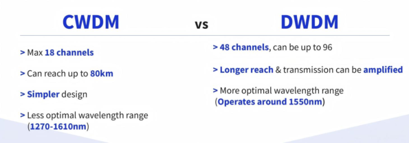
CWDM and DWDM are not competitors. They are complementary tools optimized for different layers of the network stack.
The 6.3-nanometer temperature drift that makes CWDM possible is also what limits it. The precision that makes DWDM scalable is also what makes it expensive. Understanding this trade-off—not just memorizing specification tables—is what separates network architects from equipment buyers.

 English Home
 简体中文
简体中文 Online Message
 Skype
Skype
 QQ:20181072

