
The link was only 300 meters. A 10G-LR transceiver on each end, single-mode fiber, LC connectors. Everything checked out on paper. Yet the BER tester showed a catastrophic error rate—10⁻³ instead of the required 10⁻¹². The technician replaced the transceiver. Same result. Replaced the fiber. Same result. Then someone thought to check the optical power meter: +2.5 dBm arriving at the receiver.
The problem was not too little power. It was too much.
The 10G-LR receiver was rated for a maximum input of −3 dBm (overload point) and a minimum of −14.4 dBm (sensitivity). At +2.5 dBm, the photodiode’s transimpedance amplifier was saturated. The eye diagram collapsed. The signal was not weak—it was deafening.
A 5 dB fixed attenuator, costing less than a cup of coffee, fixed it instantly. The received power dropped to −2.5 dBm, comfortably inside the receiver’s dynamic range. BER dropped to 10⁻¹². Link stable.
This is the paradox of optical networking: we spend careers fighting loss, yet there are scenarios where excess power is the enemy. The fiber optic attenuator is not a band-aid. It is a precision calibration tool that protects the most expensive component in your link—the receiver.
Every optical receiver has two critical power thresholds:
| Parameter | Definition | Typical Value (10G-LR PIN) |
|---|---|---|
| Sensitivity (Pmin) | Minimum optical power for target BER | −14.4 dBm |
| Overload (Pmax) | Maximum optical power before distortion/saturation | −3 dBm to +0.5 dBm |
| Dynamic Range | Pmax − Pmin | 12–15 dB |
If received power falls below sensitivity, the signal is lost in noise. If it rises above overload, the receiver’s front-end amplifier saturates, the eye diagram closes, and inter-symbol interference (ISI) destroys data integrity. Neither failure is subtle—both produce bit errors, but the causes are opposite.
In a 10 km link, fiber attenuation (~0.2 dB/km) and connector losses (~0.5 dB per mated pair) drop the transmitter’s +0.5 dBm output to roughly −2 dBm at the receiver—perfectly centered in the dynamic range. But in a 300 m link, the fiber only loses 0.06 dB. The receiver sees nearly the full transmitter power. If the transmitter outputs +3 dBm and the link loss is only 1 dB, the receiver gets +2 dBm—well above the −3 dBm overload point of many 10G modules.
This is where the attenuator earns its place. It is not optional. It is mandatory engineering when link loss falls below the receiver’s dynamic range.
| Transceiver Type | Sensitivity | Overload | Dynamic Range | Attenuator Needed If Rx Power Is… |
|---|---|---|---|---|
| 10GBase-LR (PIN) | −14.4 dBm | −3 dBm | 11.4 dB | > −3 dBm (typical for links <2 km) |
| 10GBase-ER (APD) | −21 dBm | −9 dBm | 12 dB | > −9 dBm |
| XGS-PON ONU | −28 dBm | −8 dBm | 20 dB | > −8 dBm (common in Class B+ ODN) |
| 100G ZR Coherent | −18 dBm | −6 dBm | 12 dB | > −6 dBm |
| 25G SFP28 SR | −10 dBm | +3 dBm | 13 dB | Rarely needed |
Engineering Rule: If your calculated received power is within 3 dB of the overload point, specify an attenuator. If it exceeds the overload point, an attenuator is non-negotiable.
An optical attenuator is not a “partially disconnected fiber.” It is a precision device that dissipates or redirects optical energy in a controlled, repeatable, and wavelength-stable manner. There are three fundamental technologies:
Mechanism: The attenuating element is a short length of optical fiber or glass doped with metal ions (typically chromium or cobalt) that absorb photons and convert them to heat. The dopant concentration determines the attenuation value.
| Attribute | Performance |
|---|---|
| Wavelength flatness | Excellent (±0.5 dB across 1260–1625 nm) |
| Return loss | >55 dB (minimal reflection) |
| Power handling | Low–medium (~1 W max) |
| Best for | DWDM systems, high-channel-count links where wavelength-dependent loss is unacceptable |
Why it matters for DWDM: A 40-channel DWDM system spans 1530–1565 nm. If an attenuator loses 5 dB at 1530 nm but 7 dB at 1565 nm, the outer channels see 2 dB more loss than the inner channels—enough to push edge channels below sensitivity. Absorption-type attenuators maintain flat loss across the entire band.
Mechanism: Two fiber ends are separated by a controlled air gap. Light diverges from the transmitting fiber; only a fraction is captured by the receiving fiber. The gap distance determines the coupling efficiency—and therefore the attenuation.
| Attribute | Performance |
|---|---|
| Wavelength flatness | Good (±1 dB across C-band) |
| Return loss | >50 dB (with angled polish) |
| Power handling | High (>5 W possible) |
| Best for | High-power applications, test equipment, temporary setups |
Trade-off: The air gap creates a Fresnel reflection at each glass-air interface (~4% per surface). Without APC polish, this produces −14 dB reflectance—unacceptable for DWDM or analog systems. High-quality air-gap attenuators use angled ferrules to direct reflections into the cladding.
Mechanism: A partially reflective thin-film coating or a MEMS mirror reflects a controlled portion of the incoming light away from the output fiber. The remainder transmits through.
| Attribute | Performance |
|---|---|
| Wavelength flatness | Variable (depends on coating design) |
| Return loss | >45 dB (worse than absorption) |
| Power handling | Medium (~2 W) |
| Best for | Variable attenuators (VOAs), test and measurement |
MEMS VOA: A micro-electromechanical mirror tilts under electrical control, varying the amount of light deflected out of the output path. Response time is milliseconds. Used in optical power leveling, automatic gain control loops, and test systems requiring real-time adjustment.
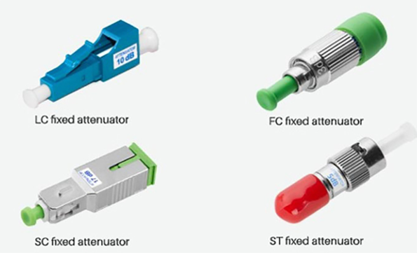
Fixed attenuators provide a single, factory-calibrated attenuation value. They are passive, require no power, and introduce no active failure points.
| Attenuation Value | Typical Use Case |
|---|---|
| 1–3 dB | Fine-tuning a link that is marginally over budget |
| 5 dB | The “universal” value for short-haul 10G-LR links |
| 10 dB | Lab testing, protecting sensitive receivers from high-power test sources |
| 15–20 dB | High-power EDFA outputs, OTDR launch fiber termination |
Physical Form Factors:
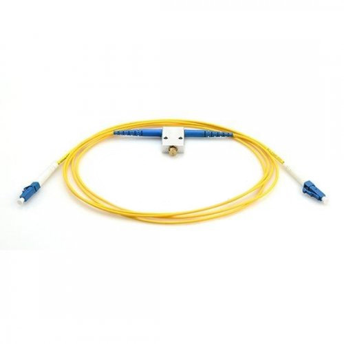
VOAs allow attenuation to be adjusted across a range (typically 0–30 dB or 0–60 dB). They are essential when:
| VOA Technology | Adjustment Method | Speed | Precision | Best For |
|---|---|---|---|---|
| Mechanical | Manual screw or micrometer | Manual | ±0.2 dB | Lab, field testing |
| MEMS | Electrical voltage | ~1 ms | ±0.1 dB | Automatic gain control, remote management |
| Motorized | Stepper motor | ~1 s | ±0.05 dB | Precision test setups |
In a DWDM system, an attenuator must perform identically across all channels. WDL measures the variation in attenuation across the operating wavelength range.
DWDM Rule: If your system uses 40+ channels, specify attenuators with WDL < ±0.5 dB. A 2 dB WDL variation across the band can push edge channels below sensitivity while center channels remain healthy—a nightmare to diagnose.
Attenuators must not create reflection points that destabilize lasers or interfere with WDM filters.
| Application | Minimum Return Loss | Polish Required |
|---|---|---|
| Digital Ethernet | >35 dB | UPC acceptable |
| DWDM / Coherent | >50 dB | UPC minimum, APC preferred |
| Analog CATV / PON | >55 dB | APC mandatory |
Critical Detail: Never use a UPC attenuator in an APC system. The flat UPC face against an angled APC ferrule creates an air gap, producing >3 dB loss and potential ferrule damage. APC attenuators are color-coded green; UPC is blue (SM) or beige (MM).
High-power applications (EDFA outputs, Raman amplifiers, fiber lasers) can deliver >1 W continuous-wave power. Standard attenuators overheat and fail. Specify high-power attenuators with:
Attenuation value drifts with temperature due to thermal expansion of air gaps or thermo-optic coefficient changes in doped glass.
A 10G-LR transceiver outputs +0.5 dBm. Over 300 m of fiber (0.06 dB loss) with two connectors (1.0 dB total), the received power is:
Rx Power = +0.5 dBm − 0.06 dB − 1.0 dB = −0.56 dBm
The receiver overloads at −3 dBm. You need an attenuator that drops the power to the middle of the dynamic range:
Target Rx = (−14.4 dBm + (−3 dBm)) / 2 ≈ −8.7 dBm
Required Attenuation = −0.56 dBm − (−8.7 dBm) = 8.14 dB
A 10 dB fixed attenuator is the standard choice, providing a 1.86 dB safety margin.
A 40-channel DWDM system with an EDFA amplifier exhibits gain tilt—the amplifier provides slightly different gain across the C-band. Channels at 1530 nm might see 20 dB gain, while channels at 1565 nm see 18 dB. After 3 amplifier spans, the 6 dB differential can push short-wavelength channels into overload while long-wavelength channels approach sensitivity.
VOAs are placed at each amplifier stage to flatten the power spectrum. Automated systems adjust VOA attenuation in real time based on channel power monitors, maintaining all channels within ±1 dB of target.
An Optical Time-Domain Reflectometer (OTDR) sends high-power pulses into fiber to detect faults. Without an attenuator on the launch fiber, the OTDR’s front-panel connector reflects the pulse back into the receiver, creating a “dead zone” where nearby events are invisible. A 10 dB launch fiber attenuator isolates the OTDR from this reflection, clearing the first 50–100 meters for accurate measurement.
In GPON/XGS-PON, the OLT transmits at +2 to +6 dBm. If an ONU is located only 1 km from the OLT (instead of the designed 20 km), the received power at the ONU can reach +2 dBm—above the −8 dBm overload point. A 5–10 dB attenuator at the ONU prevents saturation while maintaining margin above the −28 dBm sensitivity floor.
To characterize a receiver’s true sensitivity, a VOA is placed before the receiver. Optical power is gradually reduced while BER is monitored. The sensitivity is defined as the power level where BER reaches 10⁻¹² (or 10⁻³ for FEC systems). Without a precision VOA, this test is impossible.
Rx Power (dBm) = Tx Power (dBm) − Total Link Loss (dB)
Total link loss = fiber attenuation + connector losses + splice losses + splitter losses + margin
Target Rx = (Sensitivity + Overload) / 2
This centers the received power in the dynamic range, providing equal margin against both fading and overload.
Attenuation (dB) = Rx Power − Target Rx
Round to the nearest standard value (1, 3, 5, 7, 10, 15, 20 dB). Always choose the next higher standard value to ensure you do not undershoot and remain near overload.
| Parameter | Selection Criteria |
|---|---|
| Type | Fixed for permanent links; VOA for test/lab/AGC |
| Technology | Absorption for DWDM; air-gap for high power |
| WDL | <±0.5 dB for DWDM; <±1 dB for CWDM |
| Return loss | >50 dB for DWDM/coherent; >35 dB for Ethernet |
| Power handling | >2× expected optical power |
| Temperature | Industrial (−40°C to +85°C) for outdoor |
| Connector | Match system: LC/SC/FC, UPC or APC |
A: In theory, yes. But adding 10 km of fiber to drop 2 dB is absurdly expensive and introduces dispersion, latency, and additional failure points. Attenuators are precision tools; extra fiber is a kludge.
A: No. Attenuators are passive devices. They reduce signal power, but they do not introduce noise. However, by reducing signal power, they degrade the optical signal-to-noise ratio (OSNR) if the link already has amplifier noise. In a noise-limited system, every dB of attenuation is a dB of lost OSNR.
A: Yes, but with caution. Two 5 dB attenuators in series provide 10 dB. However, each introduces insertion loss uncertainty (±0.5 dB typical) and reflection. For critical links, use a single attenuator of the target value rather than stacking smaller ones.
A: Use a stabilized light source and power meter. Measure power without the attenuator (P1), then with the attenuator (P2). Attenuation = P1 − P2. Verify at the operating wavelength—attenuation values can vary by ±0.5 dB across the C-band.
A: Most fixed attenuators are bidirectional—they attenuate equally in both directions. However, some reflective types and all VOAs have preferred directions. Check the datasheet if using in a bidirectional link (e.g., PON).
The Fibermart fiber optic attenuator is easy to dismiss. It has no lasers, no electronics, no firmware updates. It simply makes light dimmer. Yet in the wrong hands—or the wrong specification—it can destroy a link as effectively as a fiber break.
Understanding receiver dynamic range, calculating required attenuation precisely, selecting the right technology for your wavelength regime, and respecting return loss and power handling limits transforms the attenuator from a “maybe we need one” afterthought into a critical component of your optical power budget.
In optical engineering, the absence of a needed attenuator is not a minor oversight. It is a design failure that manifests as intermittent errors, receiver damage, and unexplained downtime. The $12 attenuator prevents the $500 transceiver replacement and the $50,000 service outage. That is engineering economics at its finest.

 English Home
 简体中文
简体中文 Online Message
 Skype
Skype
 QQ:20181072

